F.grid_sample 计算细节
该采样函数的接口声明如下:
1
| torch.nn.functional.grid_sample(input, grid, mode=‘bilinear’, padding_mode=‘zeros’, align_corners=None)
|
函数内部先回将根据特征图 input 的大小将坐标规范化到 (−1,1),规范化坐标如下图所示,可以发现:特征图的坐标 (x,y) 对应的是 (w,h),这点和 Opencv 的规定相同,而不是按数学上的矩阵索引规律
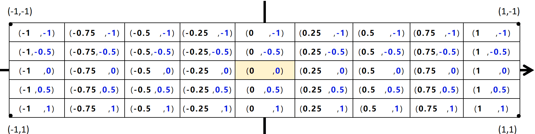
因此使用 torch.meshgird 生成网格坐标的时候,要使用 indexing='xy' 或者 transpose() 方法(以两倍上采样为例):
1
2
3
4
5
6
7
8
9
10
11
12
13
14
15
16
17
18
19
20
21
22
23
24
25
26
27
| h = torch.linspace(-h/2 + 0.5, h/2 - 0.5, h) / (h/2)
w = torch.linspace(-w/2 + 0.5, w/2 - 0.5, w) / (w/2)
init_pos = torch.stack(torch.meshgrid(w, h, indexing='xy'))
print(init_pos)
```
init_pos:
tensor([[[[-0.7500, -0.7500],
[-0.2500, -0.7500],
[ 0.2500, -0.7500],
[ 0.7500, -0.7500]],
[[-0.7500, -0.2500],
[-0.2500, -0.2500],
[ 0.2500, -0.2500],
[ 0.7500, -0.2500]],
[[-0.7500, 0.2500],
[-0.2500, 0.2500],
[ 0.2500, 0.2500],
[ 0.7500, 0.2500]],
[[-0.7500, 0.7500],
[-0.2500, 0.7500],
[ 0.2500, 0.7500],
[ 0.7500, 0.7500]]]])
```
|
上面计算过程又引出一个问题:h 和 w为什么是那样计算的?
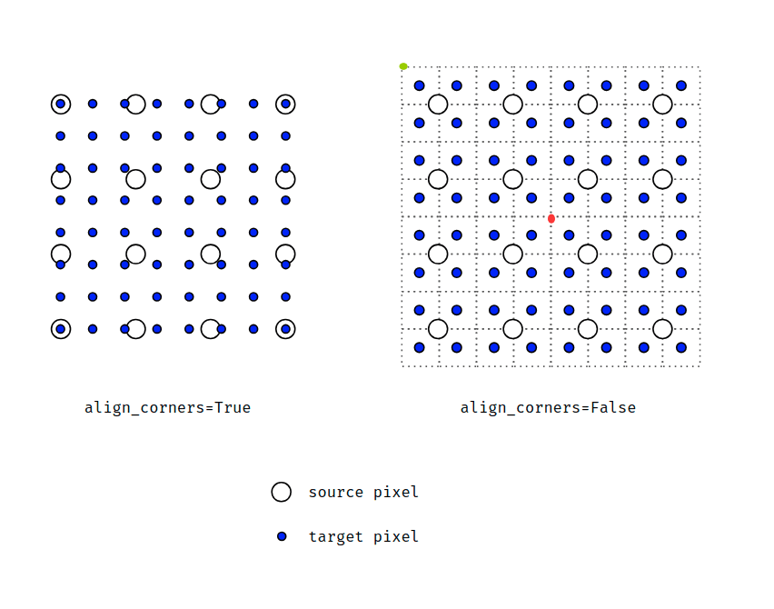
如上图所示,F.grid_sample 的 (0,0) 处坐标对应着图像的正中心(上右图中的中心红点),右上角的绿点的坐标对应着才是 (−1,1),如果我们要生成 target pixel 的坐标,那么图上的情形为 h = w = 8,(−1,0) 区间内对应有 4 个点,归一化前每个点间隔为1,则归一化前右上角坐标为 (−4,−4),最右上角 target source 坐标 (−3.5,−3.5),归一化后为 (−0.875,0.875),同样的方法可以解释上面的代码和结果
注:padding_mode 参数会对结果造成影响,在 dysample 中选用 padding_mode='border'